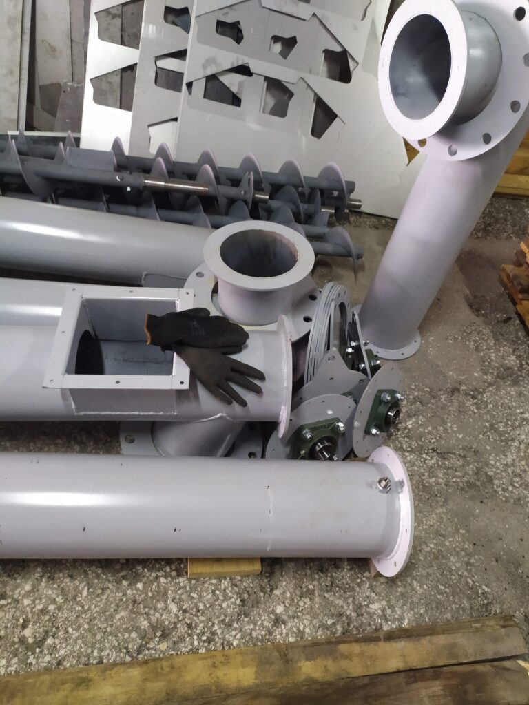
A screw conveyor looks like a simple machine: a flight rotating in a tube. But how its parts are chosen and made decides whether it runs for years without problems or keeps clogging and stopping. Here are the four main parts of a screw conveyor and what to watch for in each.
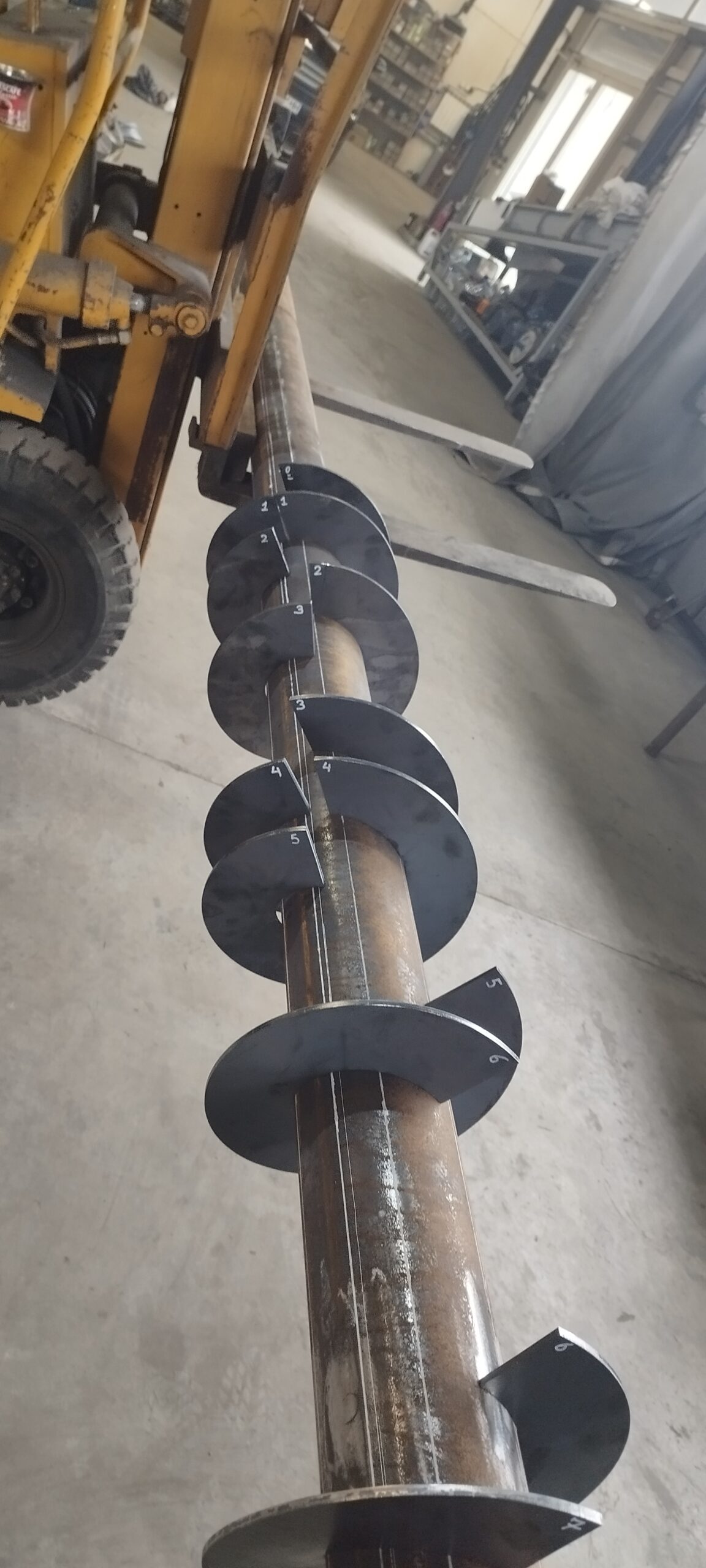
1. Screw flight
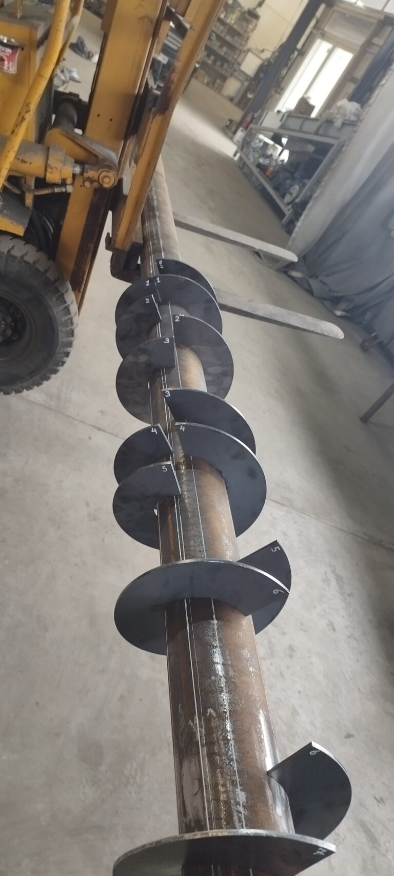
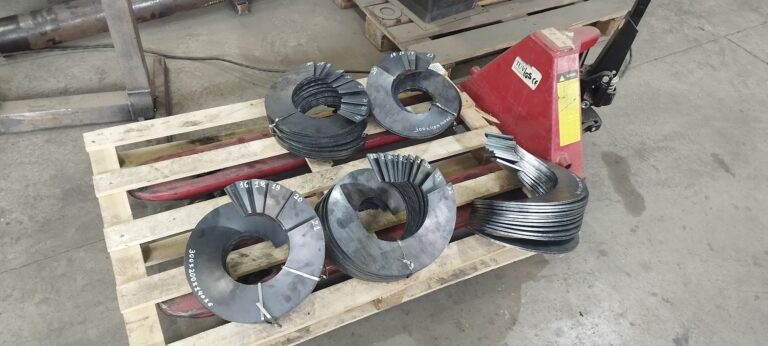
The flight is the part that pushes the material forward. It is defined by four dimensions: outside diameter, the diameter of the tube (shaft) it is welded to, pitch and thickness. Capacity and the life of the flight depend on them.
For ordinary materials the flight is made of carbon (mild) steel; for food products and aggressive environments, of AISI 304 or 316 stainless steel. For abrasive materials such as sand and aggregates, thicker or wear-resistant steel is used. For sticky and fibrous materials a shaftless flight is used. More in the article Screw flights and segments: a technical guide.
2. Casing: tube or trough
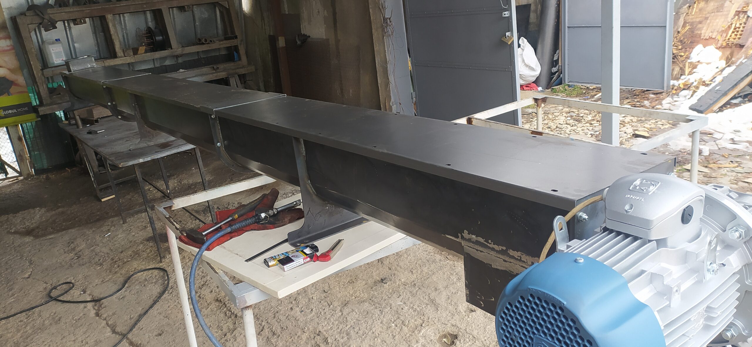
The casing encloses the flight and guides the material. A tubular screw conveyor is enclosed, does not release dust and works well on an incline. A U-trough screw conveyor has a U-shaped trough with covers – it suits larger capacities and is easier to clean and maintain.
The inlet, outlets and inspection openings are welded to the casing. Their positions are set by the machines before and after the conveyor.
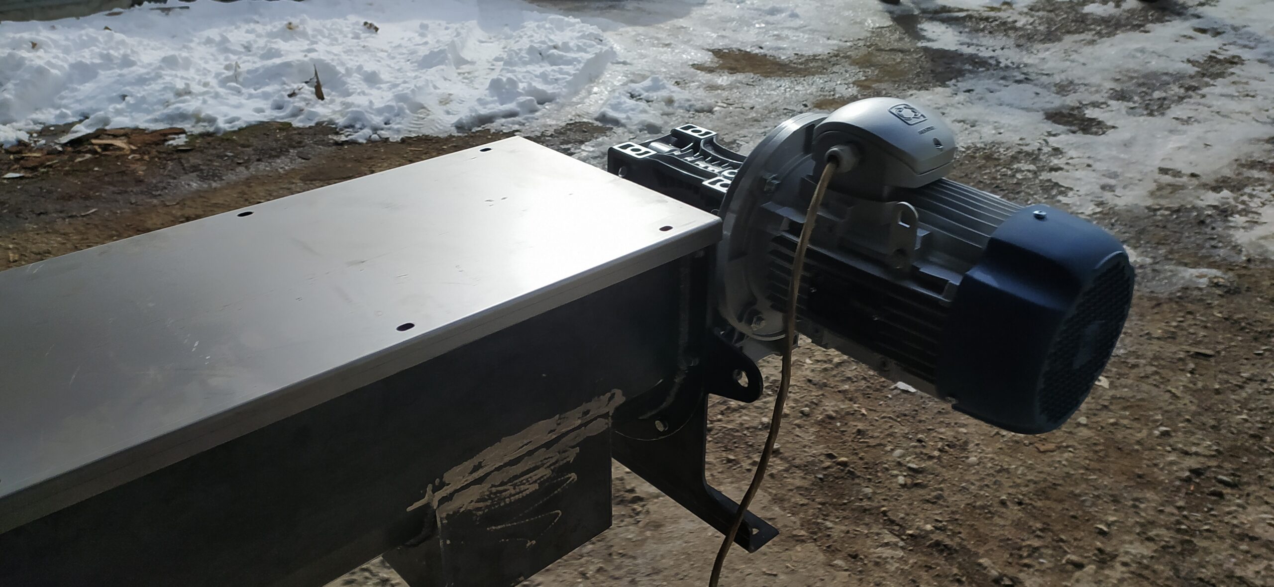
3. Drive: geared motor
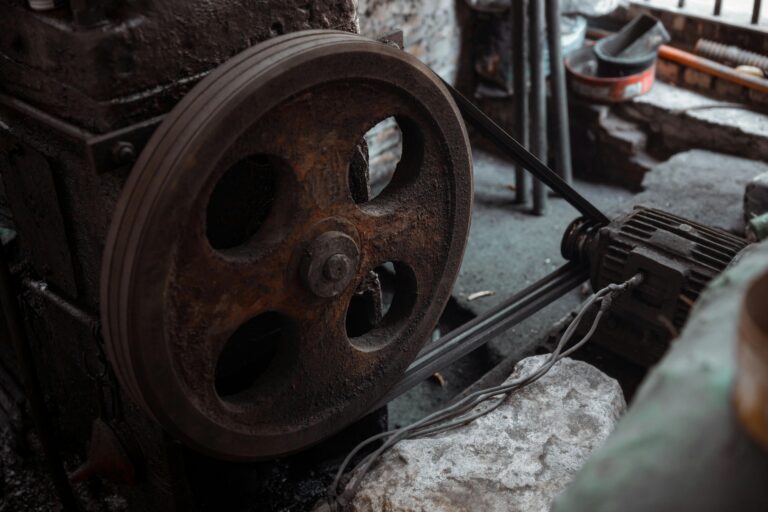
The motor turns the flight, and the gearbox reduces the speed and increases the torque. The geared motor is usually mounted directly on the conveyor shaft, without belts. The gearbox type – worm, inline helical or parallel shaft – is chosen according to torque, speed and the mounting space.
A drive that is too weak does not deliver the capacity and stalls with heavier material, so the geared motor is sized with a margin. More on the calculation in the article How to calculate screw conveyor capacity and power.
4. Bearings and seals
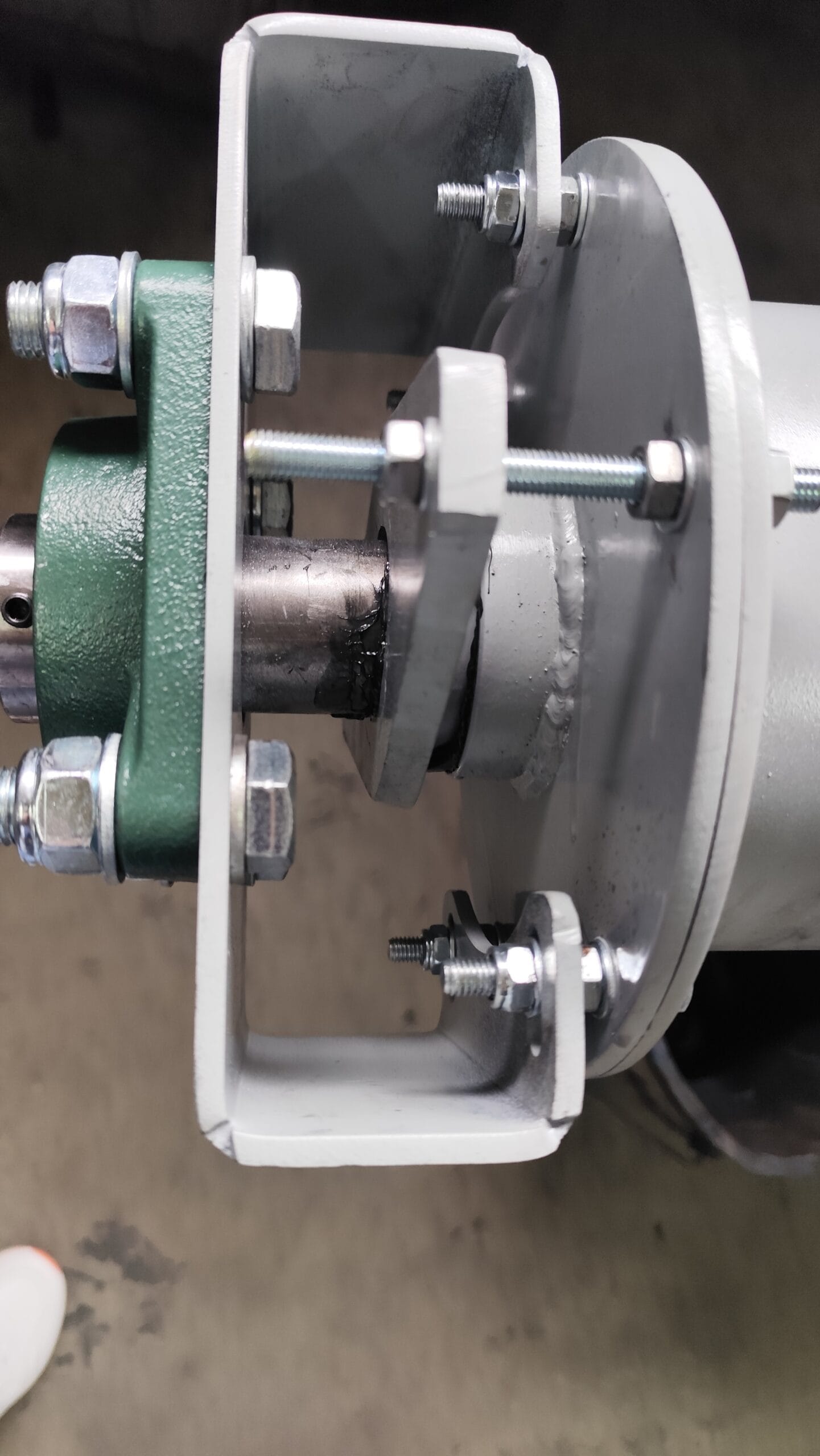
Bearings hold the shaft at both ends of the conveyor; on long conveyors, intermediate hanger bearings are added. Seals protect the bearings from material and dust and keep material from escaping. Poorly sealed bearings are a common reason for a conveyor to stop, especially with powders such as cement and flour.
5. What else completes the conveyor
Depending on the site and material, the conveyor can have a slide gate at the inlet, several outlets, supports, wheels (on mobile conveyors) or a frequency inverter to adjust capacity.
6. Common mistakes
- The flight is chosen by diameter alone, without considering the material.
- The geared motor is chosen with no margin and stalls with wet or heavier material.
- No inspection openings are provided, so cleaning is difficult.
- The bearings are not protected from dust and wear out quickly.
What to send us
Tell us the material, the capacity you need, the length and the angle the conveyor will work at. Also tell us where the material will be fed in and where it will be discharged. From this data we will propose a conveyor with the right flight, casing and drive.
Looking for a similar solution?
See the screw conveyors we manufacture, or contact us for a quotation to your specification.
Subscribe to our newsletter
Get news about completed projects, technical articles and practical solutions for conveying systems. We send only useful content – no spam.